The techniques implemented here actually will not work unless you have a new generation graphics card capable of OpenGL 4.2 or DirectX 11.
Displacement mapping, as a theory, is not new. It is in fact quite simpler in essence than bump mapping. But the implementation has a big problem.
"Real" displacement mapping (as opposed to parallax or "virtual" displacement mapping) refers to actually creating details on a surface, instead of just embellishing it with properties that it would possess if it had these details.
The problem is, in order to move the surface and carve out the details, you need vertices. Vertices you normally neither want, and more importantly you don' have.
Virtually all the techniques discussed so far (texturing, normal mapping, parallax mapping), actually have one thing in common:
They are a way to take an intricately detailed model, take a copy of it, decimate it down to its general shape, and dress the copy up with the details of the original model, giving the illusion of these details.

If you could afford millions of vertices, you wouldn't need texture maps, because you could just give each vertex the color you want. You wouldn't need normal maps, because the vertices themselves would have the correct normals. Et cetera - each vertex could contain its own info. So you take the high-detail model, take a low detail model, and dress it up with maps that the pixel shader can use to "fake" various aspects that you want.
But your only "real" entity is the vertex.
Displacement mapping goes down a different road - it is a way to actually add back these details that you removed from the high-detail model in the first place, if and when this is appropriate (for example, in a close-up when you have the possibility of shattering the user's illusion...).
The philosophy is simple:
Add vertices back to the low polygon object "somehow", when you "know" they are needed, and move them where they should be (realizing the details) using the information stored in the displacement map. The rest is exactly the same as before.
Today, in Directx11/ OpenGL 4 capable hardware, the tool to add back vertices is the tessellation stage of the graphics pipeline. This is actually a three part process - determining the presence, amount and location of new vertices, actually creating these vertices, and decorating them with the required properties. The rest is just as before. So, these stages position themselves between the Vertex and Pixel shader that we were using thus far or, in the grand scheme of things, between the Vertex and Geometry shader.
These three stages are the Tessellation Control(OpenGL) or Hull(DirectX) Shader, the Tessellator and the Tessellation Evaluation(OpenGl) or Domain(DirectX) shader.
The Tessellation Control/Hull shader is the place where you determine if you want new vertices, and how many new vertices you want, and their layout. It is a programmable stage, and its job is roughly to determine the level of detail you need.
The tessellator is configurable, not programmable, and is driven by the Hull shader. It actually creates new vertices that form the new triangles.
The Tessellation Evaluation/Domain shader will actually determine the attributes of the new vertices, the actual positions, normals etc. that will be passed to the Fragment/Pixel shader. The usual work here is interpolating between the input attributes.
And here is where actual displacement mapping happens - if you sample your heightmap at the interpolated texture position of the brand new vertex, you have a new vertex that is on the point of the heightmap, actually realizing the detail that is there.
 |
| Parallax-mapped. Quite nice already, but oblique angles and silhouettes betray the illusion of depth. The simple implementation used here also is limited in the amount of depth it can show... |
(*) Of course, all that "no errors" does not take at all into account the quality of the implementation, or the actual bumps in the road...
 |
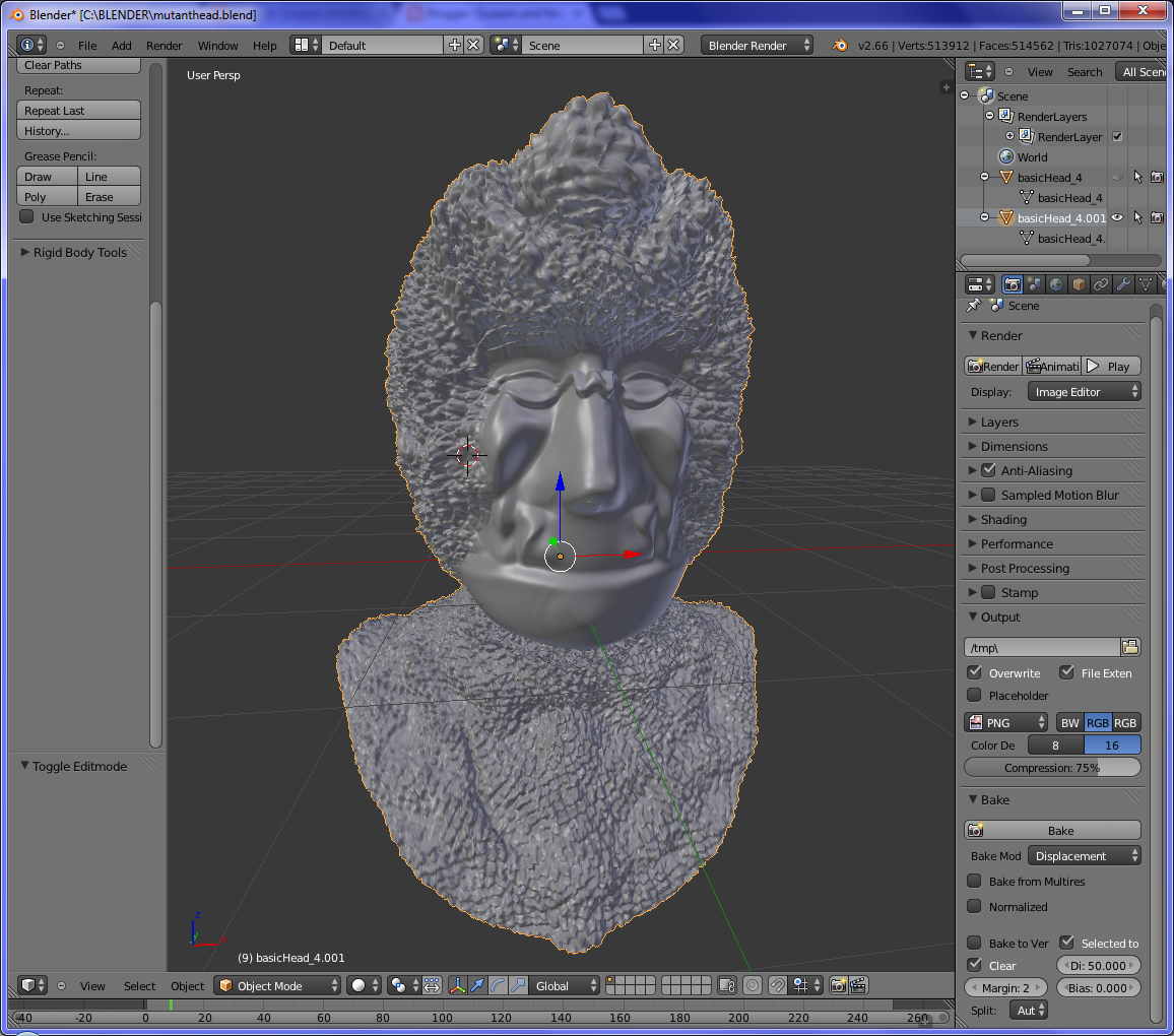
| ...while well - executed, "true" displacement mapping will be as if the polygons were there to begin with. The new vertices have actually been created. |
If you go down that road, I would suggest keeping in mind a few things.
Tessellation is a LOD tool. If you could afford the high polygon count at all times, your 3D editing program is a much, much better place to add vertices than the tesselation stage can ever be - tessellation is about adding detail when you need it, and skipping it when you don't.
Which brings us to the next point: find a smart algorithm to determine the amount of tessellation. Some classic heuristics are distance from the camera, and apparent triangle area.
Also, keep in mind that a candidate for tessellation should play nice to begin with. Very sharp triangles do not play nice. Triangles that don't have oblique angles, do.
Last, but definitely not least, the tessellation control/hull shader gives you a nice place to cull things by setting their tessellation levels to zero, and you will be checking various heuristics to determine it anyway (won't you?).
One thing I have not touched at all is nurbs and parametric curves in general. The input to the tessellation stage is not actually triangles, but patches of vertices that "should" act as "control points" to create the output vertices. I will not describe it here in detail, but tessellation is not just about reading from heightmaps - in fact, its first creators are rumored to have created it as a tool to realize curves. Of course, as all tools, actual use varies greatly than what was originally envisioned.
Here, we just displace the vertices along the normal of the original surface. Boilerplate code removed for simplicity. Note that in the Domain shader, as with the vertex shader, we cannot use the texture's Sample method, as the mipmap level has not been determined yet - we need to use SampleLevel and manually select the mip level.
An important note:
 You need to be aware of what the semantics of the semantic SV_DomainLocation are: For triangles, they are "Barycentric Triangle Coordinates", a very nifty way to abstract away the "shape" of a triangle.
In simple terms, it gives you the relative distance of a point relative to the vertices of a triangle, usually noted as (u,v,w), normalized so that u+v+w = 1. In that system, in order to interpolate a property X of the three vertices a b c, you just need to do Xnew = u * Xa + v* Xb + w * Xc.
Suffice it to say, this coordinate system is the easiest and fastest one to use for interpolation.
For reference, barycentric coordinates are calculated as in the diagram.
//DOMAIN SHADER
These are calculated in the constant function of the hull shader
struct TesselationFactors {
float outside[3] : SV_TessFactor;
float inside : SV_InsideTessFactor;
};
//Typical shader input. Note that these are arrays of 3 properties
struct DSin {
float3 position : HSOUT_POSITION;
float3 normal: HSOUT_NORMAL;
float2 texUv: HSOUT_TEXUV;
};
//Typical shader output: these should contain the final attributes of the vertex
//that we are evaluating
struct DSout {
float3 position: POS;
float3 normal: NORM;
float2 texUv: UV;
float4 clip_position: SV_POSITION;
};
SamplerState clamped_sampler: register(s1);
Texture2D normal_and_displacement_texture: register(t1);
//Scale and bias are necessary to translate displacement for what is meaningful
//for that particular object and displacement map. DO NOT hardcode them, this is
//hardcoded for prototyping only here. Normally, this would be part of a per-
//object constant buffer, same as, for example, material properties.
static const float cscale = .05;
static const float cbias = -.05;
//we use simple interpolation of the surrounding vertices to calculate the properties of the new vertex according to their barycentric coordinates relevant to the three vertices surrounding it.
float2 interpolate2(float3 barycentric, float2 v0, float2 v1, float2 v2)
{
return barycentric.xx * v0 + barycentric.yy * v1 + barycentric.zz * v2;
}
float3 interpolate3(float3 barycentric, float3 v0, float3 v1, float3 v2)
{
return barycentric.xxx * v0 + barycentric.yyy * v1 + barycentric.zzz * v2;
}
[domain("tri")] //we're talking about triangles
DSout main(TesselationFactors factors, float3 barycentric: SV_DomainLocation, const OutputPatch<DSin, 3> inp)
{
DSout outp;
// Determine the attributes by interpolation of the new attributes.
outp.position = interpolate3(barycentric, inp[0].position, inp[1].position, inp[2].position);
outp.texUv = interpolate2(barycentric, inp[0].texUv, inp[1].texUv, inp[2].texUv);
outp.normal = interpolate3(barycentric, inp[0].normal, inp[1].normal, inp[2].normal);
float displacement = normal_and_displacement_texture.SampleLevel(clamped_sampler, outp.texUv, 0).a * cscale + cbias;
outp.position = outp.position + normalize(outp.normal) * displacement;
outp.clip_position = mul(eyeToClip, float4(outp.position, 1));
return outp;
}
No comments:
Post a Comment